Like Us on FB

Thursday, 13 August 2015

555 Timer


555 Timer

Timers

Timers are those circuits, which provide periodic signals to a digital system which change the state of that system. In other words, those circuits, which work on the base of multivibrator changes or a device, which can be used as multivibrator is called Timer. (We will discuss Multivibrator in detail in next coming posts)

555 Timer

555 Timer is a digital monolithic integrated circuit which may be used as a clock generator. In other words, 555 Timer is a circuit which may be connected as a stable or monostable multivibrator.
555 Timer is a versatile and most usable device in the electronics circuits and designs which work for both stable and monostable states. It may provide time delay from microseconds up to many hours.
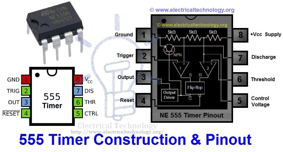
Below is the pin diagram of DIP (Dual inline Package) 555 timer with 8 pins.
Timer 555  pinouts construction working types pinout diagram
Timer 555 Pinout & Construction Diagram
555 timer is a very cheap IC which works for wide range of potential difference (typically, from 4.5 to 15V DC) and the different provided input voltages do not affect the timer output.
555 Timer is a linear device and it can be directly connected to the CMOS or TTL (Transistor – Transistor Logic) digital circuits due to its compatibility but, interfacing is must to use 555 timer with other digital circuits.

555 Timer Construction

There are lots of manufacturers who manufacture 555 timer which included the number 555 e.g. NE555, CA555, SE555, MC14 555 etc. typically, two 555 timers sandwiched inside a single chip which is called 556. Nowadays, chips are available with four 555 timers in it. These devices are available in circular IC with eight (8), DIP (Dual inline Package) with 8 pins or DIP with 14 pins.
 
Here is the simple explanation of the 8 pins of 555 Timer.

1.   Ground (GND)

It’s the common ground point of the circuit. The ground terminal of external circuit as well as power supply (Vcc) ground terminal is connected with this i.e. GND (Ground) terminal of 555 timer.

2.   Trigger

When Trigger terminal gets one –third (1/3) of the supply voltage i.e. Vcc/3 equal amplitude’s negative trigger pulse, then the circuit output changes form Low to High.

3.   Output

This terminal is used for getting output and connected with load. At any instant, its value is low or high.

4.   Reset

Without taking into account the previous state of output, by providing a trigger pulse to this terminal resets the device. I.e. Its output becomes low.

5.   Control Voltage

There are two third positive voltages of the total Supply voltages (Vcc) at control voltage terminal. Thus, it becomes a part of the comparator circuit. Generally, a capacitor is connected between ground and voltage control terminals.

6.   Threshold Voltage

Threshold voltage and control voltage is the two inputs of comparator circuit. The circuit compares the available voltage at threshold voltage terminal to the available reference voltage at control terminal.
If the available voltage at threshold terminal (Pin 6) is greater than the control voltage i.e. two-third of Vcc, then the output would be low, otherwise, it would be high.

7.    Discharge

When output is low, then Discharge terminal provides a low resistance discharge path to the externally connected capacitor. However, it acts an open circuit, when output is high.

8.   +Vcc (Supply Voltage Terminal)

Supply voltage is provided at this terminal for timer operation.
A simple 555 timer circuit is shown below in fig _ which shows the internal construction of 555 timer. According to the fig, the timer contains on two comparators, an RS flip flop, an Output stitch (output buffer) and a Discharge Transistor Q1.
 
In addition, there are three 5kΩ resistors are connected in series with 5kΩ resistor which first end is connected with Vcc (Pin 8 = Supply voltage) and the other end is connected with ground (GND = Pin 1).
Good to Know: due to the three 5kΩ series connected resistors, this IC timer chip is called 555 Timer J.
 

Working Principle of 555 Timer

555 timer Internal Function Diagram  with pinout
Internal Function Diagram of 555 Timer
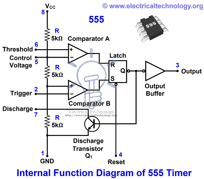
In the 555 Timer block or functional diagram, comparators are those devices which output is high, when their positive input voltage is greater than their negative input voltage and vise versa.
The voltage divider in the circuit (which contains on three series connected 5kΩ resistors), which provides the trigger level of one-third of Vcc (Vcc/3) and two-third (2/3) of threshold voltage. To understand this point, suppose the input value is 15V. In this case, the value of trigger level would be 5V as (Vcc/3 = 15V/3 = 5V). And the value of threshold level would be 10V as (Vcc x 2/3 = 15V x (2/3)) = 10V.
 
When needed, the trigger level and threshold can be adjusted by using the Control Voltage terminal (Pin 5) i.e. by changing the control voltage at Pin 5, we may change the trigger level and threshold voltage according to the required specification. However, in this case, the value of trigger and threshold would be remain equal to 1/3 Vcc and 2/3 Vcc respectively.
 
When the normal high trigger input value instantaneously reduce then the 1/3 Vcc, Then the output of Comparator B becomes High from Low, as a result, RS latch or RS Flip flop goes to “set”. When flip flop goes to set, then Output (at Point 3) becomes high. Simultaneously, the discharge transistor Q1 gets off and The output remains high until the value of normally low threshold input does not increase then the 2/3 Vcc.
 
As soon as the threshold input increase than the 2/3Vcc, then the output of comparator A becomes Low, as a result, RS flip flop get reset (because the output of comparator is directly connected to the RS flip flop’s input R as shown in the fig). When flip flop gets reset, output becomes low and discharge transistor Q1 goes to on.
 
The flip flop can be reset by applying external input reset without threshold circuit. Note that, the trigger and threshold inputs (Pin 2 and Pin 6) are controlled by externally components and the 555 timer can be used for stable or monostable operation by controlling the trigger and threshold inputs with the help of those external components.

Types of Timers

There are two basic types of 555 Timer with respect to function and operation.
  1. 555 Timer as Astable Multivibrator
  2. 555 Timer as Monostable Multivibrator

Inrush Current


Introduction to High Inrush Current in Capacitor Switching

Applications of capacitance switching are not only restricted to capacitive currents but they have their implementation in energizing process of capacitors banks, overhead lines and cables. Capacitors banks switching are known to be cause of very large value of transient voltage across the contacts of circuit breaker.
The capacitive switching characterized by commonly, switching of low to mode rate currents in industrial or public networks, and by a low rate of rise of recovery voltage. New circuit breakers (CBs) which argue a long mechanical and electrical life without maintenance seem to be best adapted to this switching duty recently developed SF6 puffer has been designed for better performance with less interrupter per pole but obviously an ideal scenario cannot be attained.
Step to removing High Inrush Current in Capacitor Switching
In power system circuits where circuit breaker have wide applications to prevent damage ,imbalance of voltages along the terminals of circuit breaker can lead to high inrush current that’s why any interruption in capacitive current can cause issues in dielectric used for switching of devices. Capacitors in capacitors bank can get damaged due to heavy inrush current.

In power system many lumped capacitors bank are present to regulate voltage, toimprove the PF (power factor) and also capacitor banks have a lot of application in filtration of high harmonics in the overall system.
In distribution process of power system there are cable networks that generates capacitive load. When any current interruption occur in the system capacitive load get charged and this charge in capacitors expose the circuit to get damaged by re-ignition of dielectric along with generating high over-voltage .
When large inrush current start flowing through substations ,the system is imposed to face consequences that occur in protection system and also while switching when voltage present in line start oscillating at slightly low frequency then its magnitude become equal to double of the peak voltage present in the circuit that can cause severe hazards. In this article it will be discussed that how we can minimize the high inrush current and what are the basic recommendations for it

Methods To Insert capacitors in order to prevent inrush current

There are two ways to place capacitors in such a way that inrush can be minimized to negligible. Both these methods are described here one by one.

A single Capacitor Bank Circuit

First Scenario
A single capacitor bank circuit and Synchronous Switching
A single capacitor bank circuit
Let’s consider the circuit above it is one phase circuit and has lumped elements for a capacitive circuit. It has a circuit breaker which close its contacts in any interruption ,one capacitor and two inductors present in the circuit assuming that resistance of the circuit is approximately is zero and value of inductor L1 is greater than L2.
A circuit breaker is present in the circuit to define the interruption in the circuit. This circuit form is called isolated bank of capacitor.
In this case current depends on the circuit parameters and initial state of the circuit. Suppose that capacitor is charge to voltage v0 at time t0. Current can be calculated from expression; 
Inrush Current in Capacitor Switching formual and equations

Where:
Methods To Insert capacitors in order to prevent inrush current

In this scenario due to damping current will decrease and overall current in the circuit will be established.

A back-to-back Capacitor Bank Circuit

Second Scenario:
This scenario is known as bank to bank capacitive switching let’s consider the diagram for it.

A back-to-back capacitor bank circuit. for high inrush current in capacitive switching and presentation
A back-to-back capacitor bank circuit.
In this case there are two capacitors and two inductors when circuit breaker is closed in interruption if their occur any dielectric breakdown at point b-b’ (i.e. difference in voltage at two contacts of circuit breaker) then expression of current can be computed as
Steps to prevent inrush current
Where:
Features and Working of SmartClose Switch

In this current can be around ten times more than the peak current present in the circuit but this current can effect only one capacitor (local) and rest of the system will be safe.

Steps to Prevent High Inrush Current

Here are some recommendations to get rid of this high inrush current.
  1. There must be a resistor present in the circuit as resistance will increase current will be utilized to some level.
  2. Extra reactance can be placed in the system because by placement of extra reactance there will be extra energy losses in the system along with reduction in effects of capacitors.

Synchronous Switching

As we know that high over voltage is created by breakdown of dielectric between thecontacts of circuit breaker, we have to remove this issue permanently . So in order to do remove issue of high over voltage it has to be made sure that when in any interruption situation a circuit breaker is closed there should be no voltage difference between the contacts of CB.
One cannot attain the ideal situation as factor of plus and minus is always there so synchronous switching is one of solution. So a device has been manufactured by the name of SmartClose Capacitor switch which can convert any bank to synchronous bank by using sensors.

Features and Working of SmartClose Switch.

SmartClose capacitor Switch
Image: hubbellpowersystems.com
It has 6 voltage sensors that detect the voltage waveform on both the capacitor side and the source side of each interrupter. A close has been command issued by a separate capacitor bank controller causes the SmartClose capacitor switch to close each interrupter independently when the voltage difference across each interrupter is zero, then close command is issued to the SC (SmartClose)will kick off zero voltage closing in all circuit.
The separate controller of each capacitor bank decides when the capacitor bank is needed; the SmartClose switch grasps that and does the whole thing by synchronous close automatically.

Wednesday, 12 August 2015

Why Battery rated in Ah (Ampere hour) and not in VA


   Battery stores charge in the form of chemical energy and then converts it into electrical energy to utilize for a specific time. The amount of available charge is the capacity of a cell or battery which may be expressed in Ah (Ampere-hour). Moreover, in a charged battery, the numbers of molecules are limited to create a flow of electron in electric circuits, so, there must be a limited number of electrons in a cell/battery which they motivate through a circuit tofully discharge. Now we have the option to rate the battery capacity in Number of flowing electrons for a specific time, but, it would be a headache, because there are a vast number of electrons in it.  So we have another option (1C (Coulomb) = 6.25 x 10¹⁸electrons, or 6,250,000,000,000,000,000 electrons.
In addition, 1A (Ampere) = 1 coulomb of electrons per second and,
1h = 3600 Seconds
Therefore;
1Ah = (1A) x (3600s) = (C/s) x (3600s) = 3600 C.
 A (1 Ampere) = 1 Coulomb per second = C/s
But,
Why make up a new unit for battery capacity rating when an old one unit is doing just fine? L
Of course! To make your lives as technicians and students more difficult.  😉  
As they do for electricity units… i.e. 1 Unit of Electricity = 1kWh = 1 board of Trade Unit…

Why Parallel Connection is Mostly Preferred over Series Connection


ADVANTAGE OF PARALLEL CIRCUIT CONNECTION OVER SERIES CIRCUIT CONNECTION.

A series circuit connection is an all or none type of circuit connection. Meaning that if one of the appliances fails, all the other appliances will also fail which is why this type of connection is good only when we want to protect a device.Advantage of parallel circuit connection over series circuit connectionWhen a fuse gets burnt for instance due to high current, then the appliance it protects will not be damaged because current will no longer reach it. While series connection is an all or none, parallel circuit connection gives you the opportunity to give the loads and the appliances their individual switch. Parallel connection offers resistance to the flow of current compared to series connection.
A 100 ohms and a 150 ohms resistors connected in parallel will have less effect on electric current compared to 50 ohms and 40 ohms resistors connected in series. In electronic devices, parallel connection is paramount. The cells in a power bank are all connected in parallel. Parallel connection makes electrical energy to last longer. The cells themselves have their internal resistance, so if they were connected in series, some of the energy will be lost overcoming the internal resistance since it’s effect is high when in series than when in parallel.

Insulation


Insulation Resistance of a Cable. why cables are insulated?
WHY CABLES ARE INSULATED? An INTRODUCTION
With the exception of power transmission cables that are on electric poles, almost all the cables that are in use today are insulated. The level or degree of insulation resistance of a cable depends on the purpose for which the cable was designed for. Apart from saving energy from being lost or dissipated to the surrounding, one paramount reason why cables are insulated is to save us from the danger of being electrocuted.
Electricity is very dangerous. The first touch can be the last touch and it never gives even a single chance. A slight touch of a cable carrying electric current can lead to a fatal accident . Our body conducts electricity partially. When our body comes in contact with a current carrying conductor, the electric current will tend to flow from the conductor then to our body. Our body being a partial conductor will not be able to conduct away the electric current. When the current too much than our body can contain, it then kills the person is question.
In order to avoid this kind of accident in our homes, it became necessary that cables be insulated. The insulation prevents current leakage as well as from reaching us thereby preventing us from being electrocuted.

WHAT IS AN INSULATOR?

An Insulator is a material or a substance that do not conduct heat or electricity. Insulators do not conduct heat or electricity because they have no free moving electrons. Conductors are said to be insulated when they are covered with an insulating materials such PVC etc. The process is called insulation. The insulator around the conductor prevents electrical energy and signals from escaping to the surrounding.

EFFECT OF TEMPERATURE ON INSULATED MATERIALS

Increase in temperature increases resistance in conductors while resistance decreases with increase in temperature in semiconductors as well as insulators. Increase in temperature can make a semiconductor a good conductor, an insulator a semiconductor.

INSULATION RESISTANCE OF A CABLE

Cable conductor is provided with an insulation of suitable thickness to avoid the leakage of current. The thickness of any cable depends on the purpose of its design. The path of current leakage in such cable is radial. The resistance or opposition offered by the insulation to the flow of current is also radial throughout its length.
For a single core cable conductor of radius r1, internal sheath radius r2, length l and insulation material resistivity ρ, the perimeter of the conductor is 2πrl. The thickness of the insulation will be given as dr.
Rins = ρdr/2πrl
When integrated, we will have:
Rins = ρ/2πl[loge r2 /r2 ]
Rins is inversely proportional to 1/l contrary to R = ρl. Where ρ (rho) is a constant known as resistivity.
There are some cables that have more than one insulating layers and more than one core. The main wire being at the center, serve as the main conductor. The other core serves the purpose of grounding and preventing the electromagnetic waves and radiations from escaping from the cabled. It serve as a shield. Cables under this category is the Coaxial cables.
Coaxial cable conducts electrical signal using an inner conductor (the inner or main conductor could be any good conductor but copper is mostly preferred because of it’s low resistivity, the copper could also be plated) is contained in mostly PVC case. Before the outer PVC case, there are two or more other insulators with either aluminum foil or copper strand between them. The cables are protected from external environment by the outermost PVC case. While voltage is passed through the inner conductor, the shield or case has little or no voltage passing through it.
The advantage of coaxial design is that electric and magnetic fields are confined to the dielectric with little leakage outside the shield. Due to the level of insulation in the cables which prevents outside electromagnetic fields and radiations from penetrating into it, interference is avoided. Since conductors with large diameter have less resistance, less electromagnetic field will be leaked. The same goes for cables withmore insulation. Knowing that weaker signals are easily interrupted by little interference, cables with more layers of insulation are always good choice for conveying such signals.

FEATURES of an INSULATED CABLE

Having noted that cable insulation resistance is determined by its purpose of design, there are some factors that an engineer would have to consider before designing a cable. Coaxial cables would require more insulation because the cable will not only prevent power leakage, it trap the electromagnetic radiations. The insulation ranging from one layer to two, three or four. Cables are engineered for different purposes.
Below are some features that insulated cables have;
  •    Heat resistant cables
  •    High insulation resistance
  •    High resistance to cuts, tears and abrasion
  •    Better mechanical and electrical properties
  •    Resistance to oil, solvent and chemicals
  •    Resistant to ozone and weathe

Smart Grid


What is a Smart Grid Then?

In simple words, an automation system between utility and consumers. This smart grid consist of advance digital system, automation, computer and control which make sure to perform a duplex “two way” communication between the power provider and load consumer. 
In a typical electrical grid system, electricity provider only will know the power failure when a costumer call them. But in case of smart grid system, if electric supply fails, service provider will automatically respond to the affected area because the components of smart grid  provides enough data i.e. from the power transformer, maintransmission and distribution system and finally, to the home supply system (you may say the utility meter).

What Things Make a Grid “Smart”?

According to the Department of Energy (United States), Four types of advance technology will transform a typical electrical grid into Smart Grid which are as follow:
  1. Fully automated and Integrated two way communication between the overall components of an electric grid.
  2. Automatic Control for power distribution, faults and repairs.
  3. Advance management panel, decision support software and mechanism.
  4. Accurate sensing and measurement technologies.
What is exactly a smart grid and their operations?Upgraded technology of smart grids has well-organized automation equipment and control system, whose response is accurate to meet the rapidly increasing demand for electricity. Time when these smart grids were not implemented all utilities companies were bound to send their respective workers to take meter reading and acquire data related to consumer.

What does a Smart Grid do?

Smart grid performs lots of smart jobs :) . Some advantages of a smart grid are stated follow:
Efficient Transmission and Distribution of Electric Power.
Quickly restore electric power after power failure due to faults.
Lower cost for operation, maintenance, management  and electricity for both utilities and consumers.
Lower electric power tariff and rates due to reduced peak demand.
Provide better options of integration of renewable energy for self power generation systems.
Improve the security and protection.

Applications of a Smart Grid System.

Deployment of Digital Technology in smart grids ensures the reliability, efficiency and accessibility to the consumers regarding all utilities which count towards the economic stability of the nation. Right at the start of transition time it become perilous to execute testing, to improve the technology by up gradation, developing and maintaining standards on a standard threshold and also application of these efficient grids serve all these problems
Basic applications of smart grids are
  • They improve the adeptness of transmission lines
  • Quick recovery after any sudden breakage/disturbance in lines and feeders
  • Cost Reduction
  • Reduction of peak demand
  • They possess the ability to be integrated with renewable energy sources on a large level which leads to sharing of load and reduction of load on large scale
What does a Smart Grid do?